


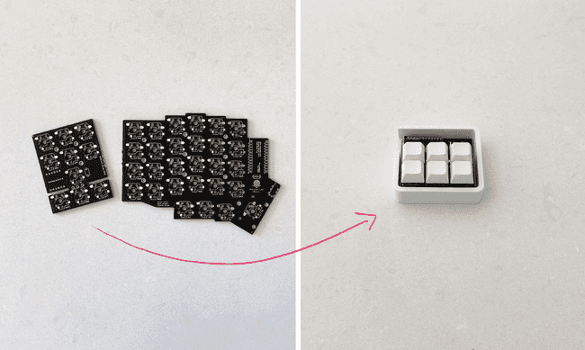
Gust is a 3x3 or 2x3 macro pad - easily customize its keys to improve your workflow.
The Gust PCB is detached from the Breeze PCB during the assembly of the Breeze Keyboard as described in this build guide. We can then use the leftover PCB part to assemble the Gust macro pad.
This guide will walk you through everything you need to know to assemble Gust.
Prerequisites
To build a keyboard using a PCB, you must already have basic experience and understanding of simple electrical components, soldering, and basic assembly using screws. We will walk you through all the steps, but keep in mind this is a DYI project. If you’re looking to buy a final product, this page is probably not for you. At the very least you’ll need a soldering iron and some solder. Lots of affordable options available on Amazon.
Hardware
These are all the items you’ll need for a complete build. Visit Keebio to find everything you need.
-
Breeze Rev1 PCBs. The kit is available on the store.
- Gust comes free with the Breeze PCB
-
Pro-Micro compatible MCU. Some options:
- Elite-C (recommended) - Buy on Keebio
- Pro-Micro clone (cheap) - One example on Amazon
-
6 Switches (MX or Kailh Choc)
- 6 x Hotswap Socket (MX or Kailh Choc)
- 6 x Keycaps of your choice
-
A Gust Macro Pad enclosure:
- Coming soon to our store
- Or make your own based on our Breeze PCB .step model
Let’s get started
1. Assemble the Breeze keyboard
As mentioned above, Gust comes as part of the Breeze PCB. Check out the Breeze build guide first. After snapping it off from the Breeze, and once you have the Gust PCB handy, we’re ready to proceed.
2. Choose switch layout (2x3 or 3x3)
After we snapped off the Gust macro board from the left hand side of the Breeze board (as described in the Breeze build guide), we’re left with the Gust macro board PCB.
Gust supports either a 3x3 layout or a 2x3 layout depending on its version. Locate the text on the Gust board that reads “Gust Rev1.x”.
- Gust Rev1 and Gust Rev1.1 - Support only 2x3
- Gust Rev1.2 - Supports either 2x3 or 3x3
2.1. Snap off the excess board
If your board supports 3x3 and you choose to build a 3x3 macro pad, skip to the next step.
If your board only supports 2x3, or if you choose to build a 2x3, we need to strip out the bottom 3 keys. After you’ve identified the top of the board, snap off the bottom part.
3. Identify the location of the MCU
Locate the text that says Place ProMicro Face Down Here. This will be the location where we will install the Pro-Micro or compatible MCU, and it’s also the top of the board.
4. Solder the hot-swap sockets
Now that you know where top of the board is, flip it over. The hot-swap sockets are installed on the bottom. Gust supports two types of hot-swap sockets, Cherry MX compatible and Kailh Low Profile Choc. Choose those that fit with your switch of choice.
Place a drop of solder on one of the pads, then attach the socket and use the soldering iron to melt it into place. Then solder the other pad. Test the first socket by plugging in one switch. Make sure it fits and that it’s in the correct orientation. Repeat for all sockets.
5. Flash the QMK firmware
Before we can attach the Pro-Micro, we need to flash it with the QMK firmware. Download the .hex file here. Then check out this guide for flashing using the QMK Toolbox.
Note that you can also customize your keymap using the Gust QMK firmware configurator.
Note: Gust Rev1.2 3x3 layout firmware is coming soon.
6. Install the Pro-Micro or compatible MCU
Gust uses a Pro-Micro (or compatible such as Elite-C) as its brain. Make sure you identify the top side by locating the text Place ProMicro Face Down Here, and the white frame around the through holes.
Use the header pins provided with your Pro-Micro. Since we’re not using all the pins, snap off the headers to leave just 6 pins on each side. Position them so that the Pro-Micro faces down. Make sure to align the right pins to the right holes. Follow the text on the PCB and match the pin names on your MCU. Insert the pins into the holes marked with the white frame. Verify your setup and then solder all pads.
Another option would be to socket the Pro-Micro. Check out this guide.
7. Optional, install the reset button
The reset button is optional since it’s possible to use tweezers or another conductive wire to reset the board when necessary. After flashing the Gust QMK firmware, you can use the keys to reset the board as well.
Insert the button next to the Pro-Micro and solder both legs.
8. Install the enclosure
Use M3x4mm screws to install the board into the enclosure.
Note: In order to fit the board in, you may need to snip off the soldered header pins on the back of the board. Carefully remove those one by one using snippers.
9. Add switches and keycaps
This is the fun part. Install the switches into the hot-swap sockets, and cap them with your favorite caps.